The Unity Line Renderer stands as a formidable instrument, affording you the capability to craft and exhibit lines within the Unity environment. This versatile tool extends its utility beyond mere line generation, enabling the creation of a myriad of captivating visual embellishments, ranging from elementary strokes to intricate configurations and designs. Integral to its functionality, the Line Renderer component accepts an array of points, allowing for intricate customization of line shapes. Furthermore, you possess the ability to tailor the Line Renderer’s appearance to your precise specifications, configuring attributes such as color, width, and vertex count to achieve the desired aesthetic and behavior.
Understanding the Unity Line Renderer
The Unity Line Renderer is a versatile tool, enabling developers to depict lines between two or more points in their games. This function primarily visualizes the trajectory between given coordinates, and its appearance is determined by parameters set for the beginning and end width. By mastering its basics, a developer can tap into its potential for a myriad of applications.
Utilizing the Line Renderer Component
Below, you’ll find a comprehensive, step-by-step tutorial on how to incorporate this essential element:
- Commence by choosing the specific game object of interest from the Hierarchy window;
- Upon highlighting your chosen game object, proceed to access the Inspector window positioned on the right-hand side;
- Next, initiate the process by clicking the ‘Add Component’ button;
- In either the search bar or the available list, diligently pinpoint and opt for the ‘Line Renderer’ component.
Customizing with Material
By default, the Unity Line Renderer might depict a pink hue, which signals the absence of a material. To customize its appearance:
- Design a unique Material according to the desired aesthetic;
- Once created, simply drag the new material and release it on the ‘material property’ slot of the Line Renderer component. This will apply the texture and color properties of the material to the line.
Diving Deep: Practical Applications
Manual Line Creation
Creating a line visually can be quickly achieved:
- Commence by establishing a fresh game entity; let’s dub it “line.”;
- Incorporate the Line Renderer Component seamlessly into this entity;
- Specify the dimensions of the line; for instance, setting it to 2 necessitates the definition of two positional points;
- Designate the initial position (indexed at 0) and the ultimate position (indexed at 1). To provide an example, you can set the coordinates from 0,0,0 to 10,10,10;
- Attach the previously generated Material to the Line Renderer;
- Presto! The line now graces the game world with its presence.
Code-Driven Line Generation
For those inclined towards a programmatic approach:
- Spawn an unadorned game object and bestow upon it the moniker “line.”;
- Append the Line Renderer Component to this entity. Should this step be inadvertently skipped, a script can effortlessly remedy the omission;
- Foster a novel script christened ‘LineDraw’ and affix it to the “line” game entity;
- Establish a connection between the custom material and the ‘mat’ property before launching the game.
Here’s a sample script for reference:
using UnityEngine;
[RequireComponent(typeof(LineRenderer))]
public class LineDraw : MonoBehaviour
{
private LineRenderer lr;
[SerializeField] private Material mat;
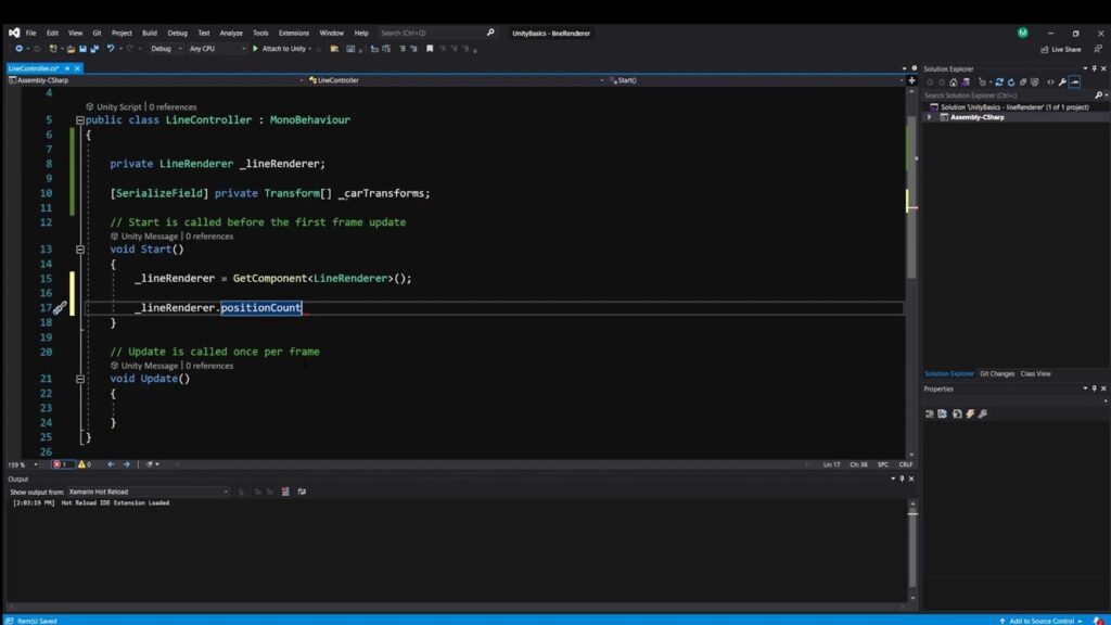
private void Start()
{
lr = GetComponent<LineRenderer>();
lr.positionCount = 2;
Vector3[] positions = new Vector3[2] { new Vector3(0, 0, 0), new Vector3(10, 10, 10) };
lr.SetPositions(positions);
lr.material = mat;
}
}This script essentially defines the line’s starting and ending points and then applies the chosen material, offering developers a dynamic way to integrate lines in their games.
Unity Line Renderer in 2D Graphics
While Unity’s core components cater primarily to 3D graphics, many of these components are versatile enough to be adapted for 2D projects. One such component is the Line Renderer. Originally designed for 3D graphics, this component can be skillfully used for 2D graphics with a simple trick.
To utilize the Line Renderer for 2D graphics, simply constrain the z-axis values for all vertices or points to a fixed number, commonly zero. By doing so, the renderer’s output simulates a 2D visual on the screen.
Drawing a Triangle
- Setup: Begin by creating a new game object in Unity. Name it “Triangle” for clarity;
- Add Component: Navigate to the object’s properties and attach the Line Renderer component;
- Looping: Activate the ‘Loop’ checkbox to ensure the start and end points of the triangle connect;
- Vertex Configuration: Adjust the positions array size to three, representing the three vertices of a triangle. Input the desired coordinates for the triangle vertices. If uncertain about exact positions, input provisional values for fine-tuning later. Remember, for 2D representation, ensure the z-axis value remains consistent, preferably at zero.
Utilizing Scene Tools for Shape Creation
Unity’s Scene Tools greatly simplify the shape creation process:
- Point Addition: Locate the Scene Tool property within the Line Renderer. Here, clicking on the ‘+’ symbol permits point addition directly within the Unity Editor’s scene view;
- Triangle Completion: In the scene view, click thrice at different locations. These represent the triangle’s vertices;
- End Point Addition: Click on the ‘+’ symbol once again to halt the point addition process;
- Vertex Adjustment: Should there be a need for any adjustments, utilize the ‘Edit’ button adjacent to the ‘+’ symbol. Drag the vertices to achieve the desired shape and alignment.
Drawing a Triangle through Scripting
For those with a coding inclination, Unity allows for shape creation using scripts. Here’s a method to script a triangle with specific vertices:
- Initialization: Generate a new game object and christen it “Triangle.” Following this, integrate a new script named “DrawTriangle.”;
- Scripting: The provided code offers a template to script the triangle’s vertices and appearance.
using UnityEngine;

[RequireComponent(typeof(LineRenderer))]
public class DrawTriangle : MonoBehaviour
{
    private LineRenderer lr;
    [SerializeField] private Material mat;

    private void Start()
    {
        lr = GetComponent<LineRenderer>();
        lr.positionCount = 3;
        Vector3[] triangleVertices = new Vector3[3]
        {
            new Vector3(0, 1, 0),
            new Vector3(1, -1, 0),
            new Vector3(-1, -1, 0)
        };
        lr.SetPositions(triangleVertices);
        lr.material = mat;
        lr.loop = true;
    }
}
By following these steps and techniques, users can effectively harness it for 2D graphics, expanding its versatility beyond its primary 3D functions.
Creating Detailed Complex Polygons with Unity Line Renderer
Crafting Sophisticated Polygons with Unity’s Line Renderer and Precise Positioning:
Harness the power of Unity’s Line Renderer to effortlessly mold complex polygonal designs. Dive into this detailed, step-by-step tutorial to master the art of constructing these advanced polygons:
Preliminary Arrangements:
- Initiate the process by spawning an empty game entity. Label this freshly minted entity as ‘Polygon.’;
- Proceed by attaching the ‘Line Renderer’ component to your ‘Polygon’ entity.
Loop Customization:
For a flawless and continuous polygon contour, activate the loop functionality.
Defining Positions:
- Adjust the dimensions of the position array in alignment with the specific polygon you envision. As an illustration, a hexagon calls for 6 distinct positions;
- Fill the position array with 6 Vector3 data points. If exact coordinates are elusive, opt for estimated values. It’s crucial for 2D configurations to maintain a z-value of 0 across all positions.
On-Scene Position Refinement:
- Navigate to the scene toolbox and select the editing symbol;
- Manipulate the coordinates directly within the Scene perspective until your polygon mirrors your vision.
Algorithmic Creation of Adaptable Polygon Designs:
Tapping into coding to spawn adaptable polygon configurations offers unparalleled versatility. Delve into this in-depth guide to uncover more:
User Inputs:
- Capture the total number of vertices from the user;
- Obtain an initial starting point.
Calculating Rotation:
The rotation angle depends on the number of vertices. For a square (4 vertices), it would be 90 degrees (360/4).
Script Creation:
Generate a new script named ‘DrawPolygon’.
Incorporate the following script, ensuring that it’s tailored to your needs:
using UnityEngine;

[RequireComponent(typeof(LineRenderer))]
public class DrawPolygon : MonoBehaviour
{
    [SerializeField] int Vertices;
    [SerializeField] Vector3 initialPos;
    LineRenderer lr;

    void Start()
    {
        lr = GetComponent<LineRenderer>();
        lr.positionCount = Vertices;
        lr.startWidth = 0.25f;
        lr.endWidth = 0.25f;

        Vector3[] positions = new Vector3[Vertices];
        positions[0] = initialPos;

        for(int i = 1; i < Vertices; i++)
        {
            positions[i] = Quaternion.Euler(0, 0, 360 * i / Vertices) * initialPos;
        }

        lr.SetPositions(positions);
        lr.loop = true;
    }
}
Creating a Dynamic Blast Wave with Unity Line Renderer
A blast wave can profoundly elevate your gaming immersion, catapulting it to unprecedented levels of interaction. In Unity, achieving this sensation is simpler than you might think. Using the Unity Line Renderer’s capabilities, you can create a captivating horizontal blast wave, adding a vibrant energy to your game. Let’s dive into this detailed guide, and I’ll lead you through each phase diligently.
The foundation of this extraordinary blast wave effect lies in the Line Renderer component. To begin, we’ll delve into a series of mathematical calculations, carefully plotting points on a circular path. As our blast wave’s radius expands, we’ll continuously adjust the Line Renderer’s position, resulting in a constantly evolving visual display.
Calculate the angle between each point on the circle by dividing 360 by the number of points you desire. This will help evenly distribute the points around the circumference.
anglebetweenPoints = 360 / pointCount;
In our game, which is set in the XZ plane, we need to find the positions in the X and Z axes. You can achieve this by using trigonometric functions like Sin and Cos applied to the angles and then multiplying them by the radius to obtain the positions. Ensure that the last position matches the first one to close the loop.
for (int i = 0; i < pointCount - 1; i++)
{
    float angle = anglebetweenPoints * i * Mathf.Deg2Rad;
    positions[i] = new Vector3(Mathf.Sin(angle), 0, Mathf.Cos(angle));
}
positions[pointCount - 1] = positions[0];
In your update function, increment the radius while ensuring it doesn't exceed the maximum desired radius. Set the Line Renderer's positions accordingly and adjust the width multiplier for a visually pleasing effect.

csharp
Copy code
if (radius <= maxRadius)
{
    SetPositions();
    radius += Time.deltaTime * speed;
    lr.widthMultiplier = (maxRadius - radius) / maxRadius;
}
Adding Physics Force to Move Objects
Now that we’ve achieved the visual aspect of the blast wave, let’s make it interact with objects within its radius. We’ll use Unity’s Physics overlap sphere function to identify colliders within the specified blast radius. To apply force to these objects, you’ll need to ensure they have Rigidbody components attached.
Here’s how the code looks:
col = Physics.OverlapSphere(transform.position, radius);
foreach (var i in col)
{
    i.gameObject.GetComponent<Rigidbody>().AddForce((i.transform.position - transform.position) * forceval, ForceMode.Impulse);
}
Combining It All Together
With all these pieces in place, you’re ready to witness your blast wave in action. Create a new empty GameObject in the Unity Hierarchy window and attach the provided script to it. Don’t forget to add a Line Renderer component. Customize the Line Renderer’s material to your liking and uncheck the “Use World Space” option for the best results.
Here’s the complete script to bring your blast wave to life:
using UnityEngine;

public class BlastScript : MonoBehaviour
{
    // Variables and initialization here...

    void Start()
    {
        // Initialization and setup...
    }

    void FixedUpdate()
    {
        // Code for radius expansion and applying forces...
    }

    void ApplyForce()
    {
        // Code for applying forces to objects within the blast radius...
    }

    void SetPositions()
    {
        // Code for setting Line Renderer positions...
    }
}
With this step-by-step guide and the provided script, you can easily create an impressive blast wave effect that not only looks visually stunning but also interacts with objects in your game world, adding an exciting layer of realism and excitement. Dive in and let your creativity explode!
Conclusion
In conclusion, the Unity Line Renderer is a versatile and powerful tool that can enhance the visual appeal and functionality of your Unity projects. This ultimate guide has taken you through the fundamentals of it, including its basic components and settings, as well as advanced techniques and creative applications.
We’ve explored how Line Renderer can be used for a wide range of purposes, from creating laser beams and trails to implementing dynamic visual effects and even simulating complex behaviors. With the knowledge gained from this guide, you now have the tools to bring your game or interactive application to life in ways you may not have thought possible.